About Microwave
Radios
With modern microwave
technology, you can connect two or more facilities quickly and
easily. Because you own your own network, we can design the system
to meet your specific requirements. Such competitive technologies as
fiber, LEC, T-1s, and xDSL all require third party service for
transmission, so the user is subject to the availability and quality
of the service provider. In contrast, the microwave user can
establish connectivity quickly and need not rely on the political
"right of way" access permission associated with fiber or LEC T-1
connectivity. With modern microwave technology, you also benefit
from the relatively low fixed costs associated with constructing the
link or links and the rarity of recurring service costs.
The Market
The traditional markets for microwave
are long distance telephony carriers, private network operations,
utilities, and the military. More recently, cellular operations,
CLECs, and ISPs have become strong users of microwave.
Cellular, PCS, and GSM Cellular carriers often
face aggressive schedules to provide expanded service for their
customers and continue generating immediate return on investment. In
order to expand their networks, cellular carriers must connect their
cell sites to switching stations. To make these connections quickly
and easily, carriers often choose microwave because it is reliable
and can be rapidly deployed. We can often commission such a system
in one day.
Local Distribution Many businesses
use microwave technology in their private networks because it offers
the fastest digital communications installation. Microwave systems
are a low cost, high security alternative to many traditional
communications system options.
Control and
Monitoring Public transport organization, such as railroads,
and other public utilities are major users of microwave. These
companies use microwaves to carry control and monitoring information
to and from power substations, pumping stations, and switching
stations.
Long Distance Carrier Connection
Long Distance Carrier Connection A significant portion of the cost
of a long distance telephone call is the cost associated with the
connection to and from the long distance carrier. Microwave radios
can connect the end user to the long distance carrier and
significantly reduce cost. In areas where long distance service is
available but local lines are not, microwave can provide the "last
mile" connection. See our section on wireless local loops.
Disaster Recovery Natural disaster can wreak
havoc on a telephone network and its supporting infrastructure.
Utilities often use microwave systems to restore communications
while replacing damaged infrastructure.
|
|
Full Line of Microwave
Radios
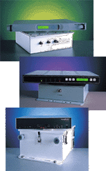
GNS offers a
comprehensive line of wireless connectivity products that meet the
communications needs for data, voice and video networks. Our
solutions deliver outstanding flexibility and performance for a
variety of short and long-haul wireless applications including those
associated with PCS, cellular, utilities, government, and private
industry.
|
|
This full line of wireless
transmission products includes the following:
- Spread Spectrum radios operating at 900 MHz as well as 2.4 and
5.7 GHz (Un-licensed operation in the ISM bands)
- Licensed frequency equipment operating from 2 to 38 GHz
Get exceptional speed,
reliability, and economy from the GNS. Point to point or point to
multipoint - whatever your needs, we have equipment covering a full
range of data rates, transmit frequencies, and output power
requirements.
|
Spread Spectrum
(Unlicensed)
Our family of
high-speed, spread spectrum radios provide highly reliable
communication links among points located up to 64 km (40 miles)
apart. Because these radios use military technology, we can
establish links in a matter of days without lengthy and costly
licensing delays. Moreover, they can scramble signals (based upon
the spreading factor) perform well in hostile environments because
they feature excellent immunity from both noise and interference.
Operating in the 2.4 GHz and 5.7 GHz ISM bands, these radios consist
of fractional T1, full T1 or E1, and multiple T-1 (high Bandwidth)
direct sequence spread spectrum (DSSS) technology. All of these are
ideal for temporary installations or more permanent "last mile" and
PCS site connections.
Applications include the following:
- Local bypass
- Cell site connections
- Alternate routing
- Redundancy
- Temporary links
- Disaster recovery
- Video conferencing
- Distance learning
- Internet access
- Voice-over IP
Features
include the following:
- More than 6 models for full duplex T1/E1 and fractional T1/E1
communications up to 4 T1/E1
- Rapid, reliable links to cellular or PCS base station
- Easy installation, operation, and maintenance
- High system gain and forward error correction
- As many as three service channels
- Wide temperature range
- Front panel monitoring and advanced loopback operations
- Network management system
- Forward error correction
|
100/200/400 Series I Digital Microwave
Radios
|
Model
100-I Specifications
Model
200-I Specifications
Model
400-I Specifications
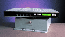
The 100, 200 & 400 Series I wireless terminals provide a
highly reliable, full-duplex data link between points located as
many as 40 miles apart. Available for operation in the unlicensed
2.4 GHz and 5.7 GHz ISM bands (industrial, scientific and medical),
the model 1050 and model 6050 both support data rates from 56Kb/s up
to 4T1/E1 data rates. The three different available user data
interfaces are V.35, DSX-1, and G.703. The data rate and clock
source are both front panel configurable. All radios use a FEC codec
for enhanced data reliability against errors caused by noise spikes,
fades, or other extraneous problems. An |
 |
on-board micro controller
controls the user interface and provides intelligent operation and
numerous self-test features. Some of the self-diagnostic tools
include such built in test equipment (BITE) functions as BER, near
and far-end Loopback functions, and alarm outputs (contact
closures). The personnel in a central monitoring facility can use
the network management system (NMS) to manage large networks of
these products remotely, and the NMS is simple network management
protocol (SNMP) compliant.
Each link has at least two end
points, You can, however, develop more complicated networks. As a
minimum, each facility has the following equipment: indoor modem
unit that is installed near the users' data equipment, an outdoor RF
unit, and an antenna that is typically 2-8 feet in diameter. With
this flexible equipment configuration, you can separate the antenna
and the data equipment without any degradation of link performance,
and a single coaxial cable provides all the necessary interface
signals. Moreover, the various antenna sizes available permit link
operation over a wide range of distances. An optional antenna
alignment unit (AAU) that provides various indicators for correct
antenna pointing is available for installers. The AAU furnishes a DC
voltage proportional to the received signal, which can be read by a
meter. An audio tone with a frequency proportional to the received
strength is provides hands-free antenna alignment. The Model 400, a
4xT1 or E1 solution for voice and data applications between two
locations as far apart as 30 miles or 50 kilometers, delivers very
low BER links that are highly immune to interference. Using spread
spectrum microwave transmission, two Model 400s with line-of-sight
access create a robust wireless link. These links are ideal for
public and private networks, frame relay applications, and last-mile
feeders into fiber-optic and satellite networks. Applications
include wireless local loop (WLL), wide area networking (WAN),
metropolitan area networking (MAN, and cell-site
interconnections.
These radios incorporate direct sequence
spread spectrum (DSSS) technology. Originally developed by the US
military for its coding capabilities, DSSS radios are now
commercially available and offer the following unique
benefits:
- Because these radios have a spreading effect on the data
signal, unlicensed operation means little or no delay in building
your data network. The data stream is spread over a bandwidth ten
times normal; however; this spreading effect reduces the energy
density of the signal. The new signal resembles noise, and the
code used for spreading is usually referred to as a pseudo noise
code (PN code). This lack of energy density is quite different
than most other forms of radio communication and is a major reason
these radios can operate without licenses. Essentially, the energy
of the signal is so spread out over its larger bandwidth that it
contributes very little to background noise and can usually be
operated in the same geographic region with other similar radios
without creating interference. The level of interference is one of
the main criteria used by the regulatory government agencies to
determine rules for new services or operations.
- Extremely reliable and robust, these radios can operate
properly with extremely low input signals. The rated specification
is operation down to - 91dBm input level or a receiver level of
one-trillionth of a watt for proper operation. The spread factor
reduces the effects of noise and other interfering signals
permitting operation in extremely hostile environments.
- These radios provide data encryption. The PN code used for
spreading and de-spreading the signal also breaks the data up into
tiny pieces called chips. The spreading process encodes the
transmitted signal, and the code is virtually unbreakable without
knowledge of the PN code. Besides the tremendous benefits offered
because of the inherent DSSS circuitry, these radios incorporate a
number of high tech features that also have tremendous user
benefits including:
- Outdoor RF unit that operates in the -40 to +55 degrees
Celsius temperature range is housed in a rugged, weatherproof
NEMA-4 enclosure. The outdoor unit mounts directly next to the
antenna and eliminates costly waveguide runs and the associated
pressurization equipment. In addition, the wind loads associated
with waveguide are eliminated because inexpensive, small
cross-section coaxial cable is used to route the signals from
the indoor modem to the outdoor RF unit. The wide operating
temperature permits continuous operation for the most demanding
applications in some of the most hostile locations around the
world.
- User friendly design incorporates micro-controller
technology with an easy-to-use LCD interface with menus that you
can use to configure your radios. The self test and loopback
features facilitate identification of failed network components.
In addition the optional network management system uses code
that is SMNP compliant. Alarms at the rear of the indoor chassis
can drive other circuits in the event of a system
failure.
- With the optional NMS, you can monitor, configure, and
control the system from a remote office. The following are key
features of the NMS:
- PC-based
- Graphical point and click
- SNMP gateway
- Alarm reporting
- Remote control
- Configuration management
- Operates over dial telephone lines or in-band on the RF
channel
The 1050/6050/400 series of wireless terminals are
highly reliable, easy-to-use, flexible communications paths for a
variety of modern telecommunications and business
applications.
|
1100/200/400 Series II Digital Microwave
Radios
|
Model
100-II Specifications
Model
200-II Specifications
Model
400-II Specifications
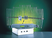
The 100/200/400 Series ll Microwave Radios, which operate in
the 2.4 GHz and 5.7 GHz ISM bands (industrial, scientific and
medical) support up to 4T1/E1 data rates, and you can use them for
wireless links with path lengths over 40 miles. All T1 radios use
forward error correction (FEC), for short-term data errors caused by
noise spikes, fades, or other extraneous problems. An on-board
micro-controller controls the user interface and provides
intelligent operation with liquid crystal display (LCD), numerous
self-test features, alarm outputs, and its NMS complies SNMP.
|
|
The 4T1 or 4E1 model, which is
backward compatible with existing radios, is an easy and inexpensive
way to migrate from a single T1 (or E1) circuit to four connections.
Along any existing path, you need change only the upgrade because
the other parts of the link are fully compatible with these new,
higher speed models. New customers can also take advantage of this
improved capability. They can order the four-channel versions from
the start or, if they prefer, start with a single T-1 circuit and
upgrade as necessary. Either way, these radios offer the finest
technology and an excellent way to take control of your need for
high-speed data circuits without incurring a high monthly telco
bill. The Series II radios incorporate direct sequence spread
spectrum (DSSS) technology. Originally developed by the US military
for its coding capabilities, DSSS radios are now commercially
available and offer the following unique benefits:
- Because these radios have a spreading effect on the data
signal, unlicensed operation means little or no delay in building
your data network. The T-1 data stream is spread over a bandwidth
ten times normal; however; this spreading effect reduces the
energy density of the signal. The new signal resembles noise, and
the code used for spreading is usually referred to as a pseudo
noise code (PN code). This lack of energy density is quite
different than most other forms of radio communication and is a
major reason these radios can operate without licenses.
Essentially, the energy of the signal is so spread out over its
larger bandwidth that it contributes very little to background
noise and can usually be operated in the same geographic region
with other similar radios without creating interference. The level
of interference is one of the main criteria used by the regulatory
government agencies to determine rules for new services or
operations.
- Extremely reliable and robust, these radios can operate
properly with extremely low input signals. The rated specification
is operation down to - 90dBm input level or a receiver level of
one-trillionth of a watt for proper operation. The spread factor
reduces the effects of noise and other interfering signals
permitting operation in extremely hostile environments. For radios
operating in the T-1 mode, the advanced FEC circuitry provides
additional data security because the receivers circuits can
correct random data errors before the data enters the far-end
network.
- These radios provide data encryption. The PN code used for
spreading and de-spreading the signal also breaks the data up into
tiny pieces called chips. The spreading process encodes the
transmitted signal, and the code is virtually unbreakable without
knowledge of the PN code.
Besides the tremendous
benefits offered because of the DSSS circuitry, these radios
incorporate a number of high tech features that include the
following benefits:
- Outdoor RF unit that operates in the 30 +55 degrees Celsius
temperature range is housed in a rugged, weatherproof NEMA-4
enclosure. The outdoor unit mounts directly next to the antenna
and eliminates costly waveguide runs and the associated wind loads
they would place on the tower. The wide operating temperature
permits continuous operation for the most demanding applications
in some of the most hostile locations around the world.
- User friendly design incorporates micro-controller technology
with an easy-to-use LCD interface with menus that you can use to
configure your radios. The self test and loopback features
facilitate identification of failed network components. In
addition the optional network management system uses code that is
SMNP compliant. Alarms at the rear of the indoor chassis can drive
other circuits in the event of a system failure.
- The radios have built-in performance monitoring. By monitoring
some of the various performance parameters, a maintenance engineer
or technician can see a failure occurring before it becomes
catastrophic. For example, the T-1 radios have a feature with
which operators can monitor the Bit Error Rate (BER) of the
circuitry before the FEC circuit. This parameter, called pre-FEC
BER, can be very useful because it yields a figure of merit
concerning link operation. Under normal operation, this value is
very low, often zero. If you keep a simple log of this parameter,
any rise in the historic value may indicate that the link is
beginning to fail. Other parameters can help determine the cause
of the failure, so that you can repair or replace the failing
portion. When properly used, these features can by provide the
necessary maintenance information and minimize downtime.
|
Licensed Frequencies -
FSK
QAM
Compact
Our high performance, spectrally efficient,
digital microwave radios are designed for medium to long haul
applications. These radios operate in the 2 GHz to 38GHz frequency
bands and are available in a wide range of data rates. Typical
applications include cellular infrastructure, cell site backhaul and
backhaul voice traffic, campus internet working and private
networks. Available in both protected and non protected
configurations, these radios will carry up to a full E3+E1 or DS3.
Protected systems provide fully redundant transmitter and receiver
components.
|
|
Family of Licensed Microwave
Radios
We use a custom application specific integrated
circuit (ASIC) that has a consistently repeatable design and uses
high spectral efficiency modulation schemes. The ASIC contributes to
the overall robustness of the communication link. Systems that use
separate digital interface units (DIUs) and indoor or outdoor RFUs
are the ultimate in system flexibility and the efficient use of
microwave power because, in most cases, short, low loss jumper
cables replace long, expensive waveguide installations. This feature
eliminates the waveguide purchase cost and its associated
connectors, mounting hardware, pressurization equipment, and
installation. In addition, it eliminates tower loading because you
can install it on towers that might otherwise be unusable because of
their capacity. Many existing towers have little or no additional
headroom for tower and wind loading, and the upgrades to increase
the capacity are very time consuming and expensive.
Other
features include triple error correction, wide dynamic range
receivers modular design with built-in diagnostic and test
capabilities, and digital orderwire and service channel options. In
addition, you can order an integral NMS that complies with SNMP or
the commonly used TBOS so that you can continuously monitor critical
system performance parameters from remote locations. Regardless of
your licensed radio application, our family of licensed radios has a
product designed for your requirements.
|
|
FSK Plus Series - FSK
Specifications
The FSK Plus is a full featured, full band
suite of digital microwave radios designed for wireless and PCS and
PCN applications. The FSK+ is available in non protected and
protected system configurations that cover a wide range of frequency
bands from 1.5 GHz to 8 GHz and data rates as high as DS3 for both
domestic and international installations. Because of their modular
design, you can easily upgrade the FSK+ radios in the field with
factory-supplied kits.
|
 |
|
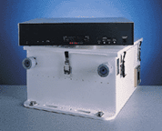
The RFU enclosures are available for
mounting indoors or outdoors. Indoor RFUs mount in a standard sized
rack and are connected to the antenna with coaxial cable or
waveguide. You can separate them for as many as 1,500 feet. For
outdoor applications, the RFU is available in a weatherproof
aluminum housing that you can wall or pole mount and connect to the
antenna with a flexible cable.
The single rack unit DIU,
mounted indoors, is the interface between user equipment and the
RFU. The DIU performs all digital processing functions and system
monitoring and requires no adjustments or tuning during or after
installation.
For ease of installation, these digital
microwave radios are fully configured and tested at the factory. An
array of built-in test capabilities eliminates the need for external
test equipment. Built-in tests and indicators include BER, receive
carrier level, transmitter and receiver phase lock, baseband
presence, data input, data output, and internal and external local
and remote loopbacks.
Typical applications for the FSK+
include cellular infrastructure, cell site back haul, and back haul
voice traffic. It supports frequency bands in the 1.5-23 GHz range
and QL, 2, 4, 8, 16 E1/DS1, E3+E1, DS3+ DS1 data
rates.
Applications
- Long and short haul network extensions
- Infrastructure support and trunk radio networks
- Oil pipeline telemetry links
Benefits
- The FSK+ extends short haul design innovations into long haul
applications.
- You can mount the RFU outdoors and eliminate long waveguide
runs.
- Extensive use of ASIC extends MTBF and reduces operational
costs
- Common DIU reduces sparing requirements.
- The FSK+ extends reduced MTTR through the use of extensive
diagnostic systems and open network management architecture
Features
- Integrated design for high reliability, extended MTBF,
increased service availability, and reduced oration costs
- Flexible indoor and outdoor radio installation for increased
performance and reduced costs
- Optional, fully redundant transmitter and receiver components,
power supplies, and cables
- Separate DIU and RFU (1500 ft/450m separation)
- Errorless receiver switching, digital filtering, and signal
equalization
- Superior link integrity, system gain, and interference
rejection for maximum flexibility in congested areas
- Triple FEC for quick and easy error detection and correction
- U1+1 errorless receiver switching protection against
atmospheric fading and equipment failures
- 4-FSK modulation for maximum system gain
- Automatic electronic DADEing
- Available in both protected and non protected configurations
that include space and frequency diversity options
- Digital orderwire capabilities
- Open architecture network management- TBOS and SNMP
- Single cable between DIU and RFU
- Compatible modules
- Expandable data capacity
- Frequency agile
- User-configured data scrambler
- MHSB with errorless switching
- Frequency Bands: 1.5, 2, 6, 7 and 8 GHz
- Data Rates - ETS1: 2, 4, 8, 16E1 and E3 - ANSI: 2, 4, 8, 16
DS1 and DS3
- Reversible Rack Mounting DIU
- Modular design, built-In diagnostic and test capabilities
- DS3/E3 Versions Include a Separate DS1/E1 wayside channel
- Expandable data capacity
- Wide dynamic range receiver
|
|
QAM Series - QAM
Specifications
The QAM series is a family of spectrally
efficient digital radios with short-haul design innovations for the
United States common carrier band long-haul applications. It
supports a range of frequency bands (6-11 GHz) and data rates (4 and
8 DSI, DS3+DS1 wayside channel). The QAM series is ideal for
applications when spectral efficiency is important. Congested
regions where customers pay for actual occupied bandwidth is one
example of such an application.
|
 |
|
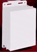
You can install the RFU indoors or
outdoors, and it contains all transmitter and receiver components.
We install Indoor mounted RFUs in EIA 19-inch standard racks and
connect them to an antenna with coaxial cable or waveguide. Outdoor
RFUs are weatherproofed aluminum for pole or wall mounted
applications.
The DIU, mounted indoors in a single rack unit,
is the interface between user equipment and the RFU. The DIU
performs all digital processing functions and monitors the system.
It does not require adjustments or tuning during or after
installation. A single coaxial cable connects the DIU to the RFU,
and this configuration reduces installation time and operational
costs.
For ease of installation, these digital microwave
radios are fully configured and plant tested. An array of built-in
test capabilities eliminates the need for external test equipment.
Built-in tests and indicators include G.821 Parameters, BER, errored
seconds (ES), severely errored seconds (SES), received signal level
(RSL), data input, data output, and internal and external local and
remote loopbacks.
Applications
- PCS and cellular backhaul
- Infrastructure support and trunk radio networks
- Oil pipeline telemetry link
- BTS to BSC traffic links or data links
- Trunk radio links for BSC to MSC applications
Benefits
- The QAM series provides short haul design innovations for the
United States, common carrier band, long haul applications.
- You can mount the RFU outdoors and eliminate long waveguide
runs.
- The smallest DIU in the industry optimizes limited base
station capacity.
- Extensive use of ASIC extends MTBF and reduces operational
costs.
- Common DIU reduces sparing requirements.
- The QAM series reduces MTTR extended through the use of
extensive diagnostic systems and open network management
architecture.
Features
- Highly integrated, short-haul design with standard components
for better reliability and economy
- Very high spectral efficiency with 16, 64, 128, or 256
quadrature amplitude modulation (QAM)
- Optional fully protected system with redundant transmitter and
receiver, power supplies, and cables
- Separate DIU and RFU (110 ft/300 m separation)
- Triple FEC for quick and easy error detection and correction
errors
- Microprocessor controlled performance monitoring
- Protection switching
- Automatic transmit power control (ATPC)
- Outdoor RFU installation and single cable connection eliminate
long waveguide runs
- Automatic DAEDing
- Errorless receiver switching, digital filtering, and signal
equalization
- Superior link availability, system gain, and interference
rejection
- Uninterrupted traffic during a switch over the receive path
- Frequency bands: lower 6 GHz, upper 6 GHz, 7/8 GHz (Industry
Canada SRSP - 307.1 and 307.7) and 10.5 GHz
- Data rates - ANSI: 4, 8DSI and DS3
- Reversible rack mounting DIU
- Single ASIC chip
- Modular design, built-in diagnostic and test capabilities
- Single cable between DIU and RFU
- Adaptive transversal equalization
- High system gain
- Wide dynamic range receiver-
- Open architecture network management including TBOS or SNMP
- User-configured data scrambler
- MHSB with errorless switching, including frequency and space
diversity options
|
COMPACT Series - Compact
Specifications
The COMPACT is a digital point-to-point
microwave radio designed for short-haul applications. The high
performance, economical COMPACT operates in the 13 GHz to 40 GHz
frequency bands and is available in the following data rates: 2, 4,
8, 16 E1/DS1, E3+E1, DS3+DSI. The COMPACT radios are available in
non-protected and protected system configurations. Protected systems
provide fully redundant transmitter and receiver components. The
radios feature advanced, highly integrated digital and microwave
components for high reliability, extended MTBF, increased service
availability, and reduced operation costs.
|
 |
|
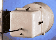
The RFU is rugged, weather tight,
lightweight, and low profile. Its direct mounting antenna interface
eliminates the need for a feeder between the RFU and the antenna,
facilitates installation, and minimizes losses. To adjust antenna
polarity, you simply rotate the RFU 90 degrees on the antenna mount.
The RFU interface supports antennas from 1-4 feet in diameter and
mounts directly to a pole as large as 5.5 inches in
diameter.
The DIU, mounted indoors in a single rack unit, is
the interface between user equipment and the RFU. The DIU performs
all digital processing functions, monitors the system, and requires
no adjustments or tuning during or after installation. A single
coaxial cable connects the DIU to the RFU and reduces installation
time and operational costs.
For ease of installation, world
access digital microwave radios are fully configured and tested at
the factory. An array of built-in test capabilities eliminates the
need for external test equipment. Built-in tests and indicators
include G.821 Parameters, BER, ES, SES, RSL, data input, data
output, and internal and external local and remote
Loopbacks.
Applications
- PCS and cellular backhaul
- Intranet work connections
- Infrastructure support
Benefits
- Integrated antenna and RFU eliminate expensive wave guide
runs.
- Extensive embedded diagnostics and configuration systems
reduce operation costs.
- Extensive use of ASIC extends MTBF and reduces operational
costs.
- Common DIU reduces sparing requirements.
- Reduced MTTR extended through the use of extensive diagnostic
systems and open network management architecture.
Features
- Fully configured and plant tested
- Target markets - CLECs, PCS and cellular markets, independent
of analog or digital cellular service, in target markets.
- Ideal applications - PCS, campus internetworking, cellular
interconnect, integration of cell sites, and private networking.
- Available in both protected and non protected configurations
- Separate frequency independent DIU and data rate independent
RFU
- Rugged, outside, compact, lightweight, weather proof aluminum
enclosure for the RFU with an integrated antenna design
- Single rack unit (1 R.U.) non-protected DIU
- Microprocessor controlled performance monitoring
- 4-FSK digital modulation for maximum system gain
- Single coaxial cable joining DIU/RFU (1,000/300m separation)
- Triple FEC for quick and easy error detection and correction
- Software controlled frequency agility
- Errorless receiver switching in protected operation
- Extensive performance monitoring including G.821
- The antenna installed directly to the RFU or separately
connected. The RFU supports antennas from 1 ft to 4 ft diameter
and mounts directly to a pole up to 5.5 inches in diameter
- Frequency bands: 13, 15, 18, 23, 26 and 38 GHz
- Data rates - ETSI: 2, 4, 8, 16E1 and E3 - ANSI: 2, 4, 8, 16
DS1 and DS3
- Reversible rack mounting DIU
- DS3/E3 versions Include a separate DS1/E1 wayside channel
- Password protection
- Wide dynamic range receiver
- Digital orderwire
- Open architecture network management including TBOS or SNMP
- User configured data scrambler
- MHSB with errorless switching
|
Wireless
LAN
Our wireless LAN offers
spread spectrum wireless networking that bridges as man as 30 miles
with as many as 10 Mbps. The product offers unique LAN to LAN and
packetized T1 and E1 connectivity and is the most flexible
multi-point system that you can configure for 2, 4 and 10 Mbps in
several combinations. The product is ideal for Internet service
providers or businesses that need high performance Internet
connectivity. Other applications include simple point-to-multipoint
private networks for schools, hospitals, city or county governments,
and a wide range of commercial applications.
Supported by
our experienced microwave radio specialists, our broad line of
wireless systems spans every wireless network application need.
|
|
SPEEDLAN Family of
Products
The SPEEDLAN wireless
LAN system offers unique LAN to LAN connectivity. You can configure
a SPEEDLAN unit for as many as three wireless LAN ports to meet
varied multi-point configuration, performance, and budget
requirements. As a multi-port bridge and optional IP/IPX Router,
SPEEDLAN reduces connectivity costs you can connect many satellite
locations with multipoint omni antennas from each of three ports. |
| With this product, you can create a
city-wide, 10 Mbps wireless backbone that spans buildings or towers
and eliminates the ongoing costs of telephone company services.
|
 |
SPEEDLAN
Benefits
- Faster than telephone company alternatives
- Goes where cable cannot go
- Quick implementation
- No right of way required
- Fast pay back; no on-going monthly service fees
- More reliable than high speed phone circuits
- Re-deployable for disaster recovery or temporary uses
SPEEDLAN Wireless
Family has significantly enhanced performance and multi-point
network capability that may attain typical ethernet speeds.
SPEEDLAN Family Features
- Plug and Play
- License free
- A 2.4 GHz frequency band or 900 MHz (2 Mbps only), direct
sequence
- Multi-point operation
- Three-in one wireless bridge
- Protocol independent
- Dynamic bandwidth allocation
- Impervious to weather
- 10 miles with standard amplified assembly
- SNMP remote monitor and configuration from Internet
- Antenna assemblies and installation kits included
- As many as 20 LED front panel displays
- Receive, transmit, and collisions for each wireless and wired
connection, system forwarding rate
- One year warranty
Typical Product
Applications
Bridge and IP/IPX Router
Functionality
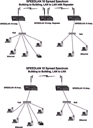
SPEEDLAN 10
comes from the factory as a transparent, MAC layer, self learning
wireless bridge with customer configurable IP and IPX routing
capability that will connect two or more Ethernet LANS. The bridge
can pass all Ethernet-like protocols including IP, IPX, and
Appletalk.
3 in 1 Bridge and
Router
Four ports are
available as ethernet, 2 Mbps or 4 Mbps wireless at 2.4 GHz or 900
MHz, and 10 Mbps at 2.4 GHz. In a multi-point wireless network,
SPEEDLAN uses one or more wireless ports with omni directional 360
degree antennas or long range directional antennas. Three different
frequency sets may segment as many as three wireless networks for
maximum throughput and availability. Each wireless segment can
accommodate multiple connections to remote locations. This ability
to operate three different wireless segments from the same chassis
reduces cost and increases configurability and usefulness of the
system for a wide range of applications.
Repeater
Functionality
If you use
two radios in a single chassis, you can create a 2 or 10 Mbps
repeater and use it to extend distance or obtain line of sight.
Dynamic Bandwidth Allocation
Wave wireless changes the
normal random timing of wireless communication to a time division
polling protocol and significantly improves multi-point
communications. Multi-point wireless network performance usually
degrades because multiple satellite locations compete for the time
of a single radio at a central location. You can configure SPEEDLAN
products to eliminate these performance problems associated with
retransmissions and acknowledgments
WIN 95 SNMP Monitor and
Configurator
You view
important network tuning statistics with an easy-to-use Windows 95
application. Network managers see and manage wireless connections
remotely with a single graphical interface. They can view statistics
for wireless packets transmitted and received from each location and
the ethernet interface to the network. Windows 95 tools include
point-to-point and multi-point antenna alignment utilities, complete
remote configuration, management, and reboot capability. They can
also monitor equipment temperature and other metrics.
Ease of Support and
Management
You can
administer SNMP wireless and wired link management from any ethernet
network or remotely from the Internet. You can upgrade software and
service the system from the Internet or through a SLIP "out of band"
management port and external modem. SNMP MIB II, Bridge MIB,
Ethernet interface MIB, and proprietary MIBs are included for the
bridge and router.They include RF signal level, quality, and noise
level.
Protocols
- IEEE 802.3 ethernet protocols
- IEEE 802.1 d transparent MAC layer bridging
- RFC compliant routing
Performance and
Configurability
Because of
SPEEDLAN flexibility, you can use the following radio interface
combinations to create backbones and wireless segments for the most
demanding multi-point data applications.
SPEEDLAN
Plus
As many as three 2
Mbps Ports
SPEEDLAN 10
- One 10 Mbps port
- One 10 Mbps port and one 2 Mbps port
- One 10 Mbps port and two 2 Mbps port
Special Features
- Optional transmission power to 4 watts EIRP
- Up to 25 miles distance with optional special high gain
antenna assemblies
- Data encryption
SPEEDLAN
10ptp
High Performance
10 Mbps Wireless-Point to Point
The SPEEDLAN 10ptp is a 10
Mbps wireless point-to-point bridge that provides a secure wireless
connection between locations at a lower cost and with more than four
times the speed of leased T1 lines.
SPEEDLAN 10ptp can
transmit data 15 miles or further for point-to-point links and is
ideal for wireless connections for ISPs, Telcos, and private data
network extensions.
The SPEEDLAN 10ptp supports connections
across town and across the street. It also is ideal for locations
where wireline is too expensive or takes too long to install. The
SPEEDLAN 10ptp represents a significant breakthrough in LAN
flexibility. It offers affordable, high speed, wireless connectivity
for the point-to- point market. This single, self-contained unit
easily plugs into a wired network segment. The SPEEDLAN 10ptp
automatically senses local traffic, builds internal address tables,
and operates retransmission and packet filtering protocols
immediately without user intervention.
The SPEEDLAN 10ptp
goes where wires cannot. Since its use involves no monthly fees or
government licenses, the SPEEDLAN 10ptp offers everything you need
create a wireless network.
SPEEDLAN 10ptp uses the FCC
license-free 2.4GHz frequency band. It is compatible with all IEEE
802.3 and 802.2 LAN device and all computer platforms and operating
systems and is completely transparent to network devices.
SPEEDLAN 10ptp
Features
- 10 Mbps data rates
- Plugs into AUI port of hub or media converter
- No software to install
- Retransmission and packet filtering protocols.
- High throughput at the MAC layer
- Protocol independent
- Secure Transmissions-DSSS coding algorithms
- One year warranty
- Antenna, cabling, lightning arrestor, and installation kit
SPEEDLAN 10ptp
Benefits
- Distances to 15 miles
- Plug and play
- License-free
- Faster than Telco lines
- Goes where cable cannot
- Quick implementation
- Redeployable
- SPEEDLAN ISP
- Wireless Ethernet metropolitan area links
All kits include antenna,
lightening arrestors, cabling and optional
amplifiers
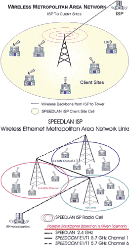
With SPEEDLAN ISP, the Internet service
provider has an alternative to using telephone company leased or
dial up lines for client access to Internet service. SPEEDLAN ISP is
a complete radio, hardware, and Windows 95/98/NT 4.0 software
solution for wireless communications that work with the SPEEDLAN
wireless base station at an ISP selected cell site or ISP office
location. Connectivity is made to the ISP without wires or telephone
company lines for a single residential or business client and can be
expanded incrementally to create an entire wireless metropolitan
area network. SPEEDLAN ISP goes where cable cannot go and expands
the client base without dependence on the telephone company
infrastructure. You can install it immediately; no need to wait for
telephone company installation.
Features
- Uses 2.4 GHz or 900 Mhz frequencies
- ISP controlled bandwidth allocation
- Plug and play ISA or PCMCIA radio
- As man as 1.6 Mbps
- As many as 8 base stations per location (384 subscribers)
- As many as 48 subscribers on-line per base station (96 in
future releases)
- Central ISP management and licensing control
- Amplification to 10 watts (international only)
- Windows 95/98/NT 4.0 subscriber software.
- Antenna, installation kit
- Optional encryption
- Optional enterprise-wide wireless base station
Benefits
- Increased revenues
- No ongoing access fees for the ISP
- Fast uploads and downloads
- Quick subscriber base expansion
- Easy redeployment
- Instant, reliable communications
- SNMP management and statistics
Distances
- 5-8 km with standard kit
- As far as 20 km with amplification
Prerequisites
ISP cell site or office location
- ISP cell site or office location
- SPEEDLAN ISP base station Kit
- Wireless ISP router
- SPEEDLAN ISP management software module subscriber site
- PC with open ISA slot or notebook computer with open PCMCIA
slot
- Windows 95/98/NT 4.0 operating system
- SPEEDLAN ISP radiocard kit
|


