|
MMDS
Broadband TRANSMITTER FOR THE 2.3
GHZ BAND
Point-Point
and Point-Multipoint
1.
System Description
A
point – multipoint (and point to point) microwave distribution system (MMDS or AM micro)
designed for the transmission of several TV program signals in the microwave
band. The AM-VSB modulated TV signals together with the FM modulated
pertaining voice channels are lined up in 8 MHz channels.
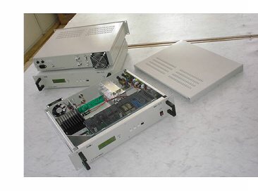
The
typical construction of the 2.3 GHz system manufactured by our partner in Hungary is shown in Fig.1. The programs
arriving from several different locations can be transferred from the
base band either in the VHF or the UHF bands into the neighboring
channels with the aid of channels units (modulators). In this case the
channels are mixed up into the VHF band on the unique modulator outputs
and a combiner takes them to a distribution amplifier. The output level
range of the distribution amplifier is approximately the same as the
output level of the modulators ( 90 – 110 dBμV at 75 Ω ).
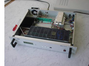
In
the MDS 230/T MDS transmitter the VHF channels are up-converted into the
2.3 GHz microwave band and amplified to the necessary level. It is
important that the adding of the transmitter’s own noise to the noise
balance should be low enough together with the intermodulation products
caused by the simultaneously transmitted channels located closely on
each other.
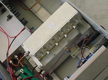
In
order to cover an area the output signals of the transmitters must be
distributed to the antenna system. A typical example is shown in the
microwave distribution network in Fig.2. where 3 dB hybrids can divide
the output signal of the transmitter into 8 parts. After the division
the new levels on each output port have to be amplified in order to give
the necessary level for each antenna required by the MMDS system. In the
same example, the 3.5 dB real attenuation of the individual microwave
hybrids will result about 10.5 – 11 dB total attenuation plus the
added attenuation of the connecting cables. In order to reach the
desired level a microwave output amplifier block must be attached to
each output with the same requirements as valid for the amplifiers of
the transmitter (low own noise and high linearity).
2.
Technical data
Input
frequency level
198 – 238
GH
Input level range
1 TV
channel 90 – 110
dBμV / 75Ω
5
TV channels 5 x 90 –
110
dBμV / 75Ω
Input impedance
75
Ω
Output frequency band
2290 – 2335 MHz (optional)
Output level (1 TV channel)
40
mW
Output level (5 TV channels)
5 x 40
mW
Output impedance
50
Ω
Output connector
“N-“
TV channel RF signal/noise
(C/N)
min. 63
dB
Output IP3 55
dBm
Output IM3 (at nominal
output levels)
min. 60
dBm
Out – of – band components’
level compared to the
carrier max. – 70
dBc
Consumption figures
(preliminary)
Mixer and preamplifier
150
W
End amplifier
150
W
from 220 V AC
max. 2
A
Temperature range
0 - +50
ºC
Storage -35 - +65
ºC
Note: The manufacturer reserves the right to change the data without
notice.
|