|
|
|
|
|
|
|
|
|
|
|
|
|
|
|
|
|
|
|
|||||
|
|
||||||||||
|
|
|
|
|
|
|
|
|
|||
|
|
|
PrimeWave
2000™ System Summary
|
 |
||||||||
 |
|
Advanced
but well proven Synchronous Code
Division Multiple Access (S-CDMA™) technologies allow efficient and
cost effective use of the Radio Frequency (RF) spectrum. All
standard telephony devices, such as telephones, faxes, and modems may be
connected to the PrimeWave 2000™ Customer Premises Equipment (CPE) using
standard interfaces. Data interfaces include X.21 and ISDN. Multiple
standard interfaces and protocols to the public switched telephony network
(PSTN) are provided through the PrimeWave 2000™ Network Interface Unit (NIU).
Telephony and data signals are transmitted to the Customer Premises
Equipment through the PrimeWave 2000™ Radio Base Unit. Multiple options
are available to tailor the system to urban, suburban and rural
environments. The
system is a highly cost effective means of rapidly providing telephone and
data services to: -
developing
countries
with little telephony infrastructure, -
fast
growing countries
that need to expand their telephone systems, and -
developed
countries
wanting to increase competitive voice and data services. PrimeWave
2000 supports: -
Voice, fax and modem transmission -
Data services to 128Kbps (X.21 interface) -
Resistance to eavesdropping (secure communications) -
Connection to all current PSTN standard interfaces -
Highest WLL subscriber capacity available -
Highest WLL transmission quality available
FeaturesTelephone interface supports all standard telephone instruments including phone, fax and modem.Customer Premises Equipment available in a variety of configurations including Single (1), Dual (2), Quad (4) and Octal (8) line telephone, X.21, ISDN and Payphone.Variable telephone line concentration from 1:1 up to 251. Intra-calling
function available. Subscriber to subscriber calling within the CPE and
independent of the PSTN.
Feature
calling services available including conference calling, call forwarding,
call waiting, call transfer, etc..
Multiple
PSTN protocols supported including CAS, CCS, C7, V5.2 and R2.
Multilevel
PSTN protocols support emergency 999 (911), hospital, police and VIP
services.
Extensive
fraud and service theft prevention features.
Billing
services available.
System
Level Parameters
Method
of Operation
Full duplex. Frequency pairs are used, one for the forward channel
and the other for the reverse channel. CDMA
Method
Direct sequence spread spectrum (DSSS), forward and reverse
channels. Spreading
Rate
2.7 Mcps. Forward
Error Correction
Trellis coding and Viterbi decoding in both forward and reverse
channels. Frequency
plan
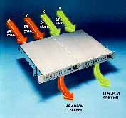
Four frequency bands currently supported: Frequency
channels
In the current supported plans, each band is divided into 14MHz
channel pairs. Each channel is divided into 4, 3.5 MHz sub channels. Encryption
Forward and reverse channels. Voice
Compression Voice mode only: A-law companding with ADPCM. A-law only for fax
and modem (ADPCM bypassed). For less bandwidth efficient cases, voice mode
can be used with A-law only, and no ADPCM compression. Equipment
Summary
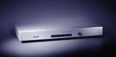
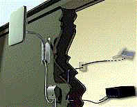
Customer
Premises Equipment (CPE) Subscriber
Unit (SU) One piece enclosure includes antenna, RF circuitry, modem,
telephone interface and data interface. Network
Termination Unit (NTU) Provides the boundary between the telephone system equipment and
customer’s equipment. Uninterruptible
Power Supply
Maintains power supply during mains power Radio
Base Unit Antenna Provides the aperture for transmission and reception of radio
signals within one cell. Radio
Base Unit (RBU) One rack of equipment that includes RF circuitry, modem, telephone
interface and data interface. Network
Interface Unit (NIU)
Provides the interface between the PSTN and the RBU, controls the
PSTN protocols System
Capacity (System = single NIU. Multiple NIUs can be supported) Active
telephone lines per RBU 100 active lines, up to 119 under ideal conditions (Note: telephone
lines can optionally be data connections). Maximum
lines per RBU Up to 2500 with 25:1 concentration. Maximum
RBUs per NIU (system) Up to 15 (assumes no NIU intra-calling. When
intra-calling is used,
more RBUs can be supported). Maximum
active lines per NIU Up to 1500. Maximum
lines per NIU (system) 10,000 lines. RBUs
per cell Variable depending on antenna, frequency and PN code selection. Interfaces Network
Interface Unit (NIU) PSTN
Physical Interface Twisted pair VF channel bank or E1 (75 or 120 Ohm). Up to 1500
ports. PSTN
Protocol Interface Flexible to accommodate all known CAS, and CCS protocols. RBU
Interface 1 to 4 E1 connections per RBU. The E1 signals can be relayed to
accommodate remote RBUs. Up to 15 RBUs can be supported from a single NIU. Power
Input -48VDC. Radio
Base Unit (RBU) NIU
Interface
One to four E1 connections. The E1 signals can be relayed to
accommodate remote RBUs. Antenna Coaxial cables of up to 100 metres connect to the antennas. For
space diversity, up to two antennas can be connected. Power
Input
24 VDC, 48VDC or 60VDC. Customer
Premises Equipment Telephone
Interface One to eight telephone lines with independent telephone numbers
using standard tip and ring signaling. Payphone One or two payphones. X.21
Data Interface One or two standard DB15 connectors. Power
Input Universal AC input. Antennas
RBU
Transmit and Receive Gain 8 dBi, max. Optional sectored antennas with increased
gain SU
Transmit and Receive Gain 18 dBi, max. Polarization
Right Hand/Left Hand Circularly Polarized (RHCP/LHCP). Transceivers
RBU
Power Amplifier Output
+35 dBm nominal. SU
Power Amplifier Output +14 dBm nominal. Modulation. Quadriphase shift key (QPSK) data modulation with
BPSK spreading. Demodulation Coherent. User
Data Rate per SU
Variable in real time to support single, dual and quad line
configurations. 32Kbps, 64Kbps, 96Kbps and 128Kbps supported. Bit
Error Rate (BER) < 10-6. Receiver
Sensitivity -114 dBm. System
Sensitivity
-111 dBm (includes the effects of multi user interference). Power
Control Reverse channel, 40 dB range. Radio
Base Unit
Reliability
25 years mean time to hardware stop. (MTTHS). Redundancy Option for N+1 redundancy on all major components to ensure
continued operation in the presence of a failure. Space
Diversity Option
A second antenna can be added to improve performance in a
multi-path environment through space diversity, when required. Maintainability All circuit cards are replaceable without interrupting system
operation and with power in (Hot Swappable). Operating
Environment -10 to +55 C, indoor. Size
One standard rack, 483 mm (19 inch) wide, 1300 mm high (27U), 450
mm deep. Cooling
Forced air cooling.
Customer
Premises Equipment
Equipment
Interfaces Subscriber Units can be configured to interface to the following: SU
Reliability 10 years mean time between failure (MTBF). SU
and NTU Environment
-30 to +55 C, Outdoor. Environmentally sealed and UV resistant. Power
Supply Environmental
-10 to +55 C, Indoor. SU
Size
41cm x 41cm x 8cm (16 x 16 x 3 inches). NTU
Size 12cm x 13cm x 6cm (4.75 x 5.25 x 2.5 inches). Power
Supply Size 19cm x 26cm x 12 cm (7.5 x 10 x 4.75 inches). Cooling
Natural convection only. Customer
Premises Equipment
Human
Interface One computer terminal controls one NIU and all connected RBUs (up
to 15). Provisioning The Control Terminal provides all necessary tools to provision the
system, including adding, reconfiguring and deleting users. Monitoring The Control Terminal allows monitoring of a wide variety of system
parameters. System health and status including data link quality, are
recorded in each RBU every 10 minutes and can be maintained for up to 48
hours. This data can be downloaded to the Control Terminal. Fault
detection and Isolation
Full set of built in tests provided to isolate failures to the
circuit board on which they occur. All faults and performance degradations
are reported to the Control Terminal. System tests, element tests and
circuit board self tests are provided. Tests are conducted automatically
but can also be initiated from the Control Terminal. Phone
Tests
Make/Break dial tone and loop back test capability is provided. Maintenance All equipment is designed for ease of maintenance. RBU can be
maintained without interrupting service. Billing Full billing data is available. Unintended
System Use
Extensive provisions to detect and defeat CPE equipment theft,
service pirating, intrusion etc.. Software
Uprgades
Upgrades can be down loaded to the NIU, RBU and SU from the Control
Terminal. SU downloads software over the air via the forward channel. TMN
Growth path to TMN services, including Q interfaces. What
is Spectral Efficiency? Spectral
efficiency is a measure of how effectively a system makes use of a limited
amount of Radio Frequency spectrum!!! It
is calculated as: AVAILABLE
CHANNELS x BIT RATE Greater
efficiency means that more voice and data traffic can be supported within
a limited frequency range.
* Available channels depend on soft-handoff percentage (typically much
less than 42) Synchronous
CDMA – Perfect for Fixed Wireless Loop Applications
The basic idea in reverse channel synchronous CDMA (S-CDMA) is that
timing offset information is fed back from the base station to the
subscriber units so that they may adjust their transmitter’s timing to
all arrive at the base station within a small fraction of a chip of each
other. This approach permits the use of truly orthogonal signature sequences
for all of the users, assuming that the number of users in the system is
no greater than the chip rate to channel symbol rate ratio. Due to the use
of orthogonal signature sequences, many
more users may be supported in a given cell or sector than in an
asynchronous CDMA system. The capacity of such an asynchronous system is
limited to the number of somewhat correlated/interfering users that can be
supported without raising the interference noise floor to an unacceptable
level. The number of users is typically about 1/3rd that of a
comparable synchronous system. S-CDMA capacity is also higher than that achievable by TDMA or FDMA
systems due to the lack of guard-bands and guard-times in isolated cell
deployments. When multi-cell deployments are considered, the capacity of
S-CDMA vastly exceeds that of a TDMA or FDMA system, due to the fact that
every cell/sector can operate on the identical frequency band (referred to
as, a frequency re-use of one). In contrast, TDMA and FDMA systems require
that adjacent cells and sectors use different frequency bands to keep
interference levels sufficiently low. In a wireless local loop telephone system where it is necessary to
achieve very high availability’s (say 99.5% or higher) large margins are
required in the link budget to combat fading. A common misconception is
that there will be no fading in the fixed wireless local loop application,
because subscriber units are not mobile. This simply is not true. Point to
point microwave links, which are completely stationary and even have very
high gain antennas, often experience fades of 40dB or higher. To combat
this problem, a fixed wireless local loop system will need to have an
effective fade margin in the order of 10dB to achieve link availability in
the order of 99.5%. With S-CDMA, this kind of fade margin is achievable because the signal
to interference ratio is so large due to the orthogonal signature
sequence. In contrast, large fade margins are simply not achievable with
an asynchronous CDMA system because in such a system the number of active
users is increased until the signal to noise and interference ratio
reaches a threshold which corresponds to a desired bit error. It is not
possible to add additional margin to the asynchronous CDMA system without
diminishing its capacity. Thus, S-CDMA provides the ability to achieve the high link availability necessary or the fixed wireless loop
application. In addition, S-CDMA benefits from the advantages of
traditional CDMA including a frequency
reuse of one (1) in multi-cell deployments, a robustness
to narrow band interference and an inherent resistance to eavesdropping due to the use of pseudo-noise spreading
codes. So
if S-CDMA is such a good idea, Why isn’t every company doing it?
L3 Communications is not starting the fixed wireless local loop product
development from scratch. Instead we are simply building upon a foundation
of spread spectrum and CDMA experience and products gained from many years
of developing robust, covert military data links. Unlike most companies,
L3 Communications has been producing spread spectrum and CDMA products for
many years and so making the technological step to S-CDMA from traditional
CDMA was not difficult. We have an innovative engineering staff that was able to solve the
fundamental problems of synchronizing the system quickly, even when
heavily loaded, and maintaining synchronization even on a multi-path
channel, with an efficient timing control loop.
Prior to this development effort, these fundamental problems scared
away other potential developers of S-CDMA technology. L3 Communications
has either been granted, or has applied for over
12 international and US patents on these inventions that make S-CDMA
possible. Finally, L3 Communications is not attempting to simply apply a mobile
system solution to the fixed wireless local loop application. Instead, we
started with a clean sheet of paper to create the system design. PrimeWave
2000 was designed from the ground up as a fixed wireless local loop
system, so that we could optimize the system design to the application and
apply fresh new ideas and the latest technology, including S-CDMA. This
approach has produced the highest
capacity and highest
performance, wireless local loop product available today. |
||||||||||||||||||||||||||||||||||||||||||||||||||
|
|