|
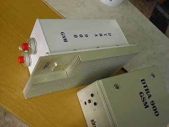
DTRA 900 GSM
Bidirectional Tower Mounted
Amplifier/Booster
Features
-
Higher transmitting (down-link) and receiving
(up-link) cell coverage
-
Higher base station receiver sensitivity
-
Longer mobile handset battery lifetime
-
Settable transmission output level (0 - 30
watts)
-
Visual display of Local Alarm and Antenna
Reflexion
-
Intelligent PC based built-in signaling system
-
Versatile connection to Remote Management
System
-
Power Supply from main voltage system
-
Easy installation, fast commissioning
without base station modification
Description
DTRA 900 GSM is the 900 MHz band
member of the equipment family developed by our partner
in the 450 - 900 – 1800/1900 MHz bands. It expands the coverage area
of the already existing 900 MHz base station using the existing equipment, cables and antenna. It is especially recommended for low
output power base station equipment (Micro-BTS) where besides the
increased sensitivity of the uplink branch it also provides a 20W
transmitter output power instead of the typical 2W. When two high level
RF channels are required the signals of two equipment can be combined using
a cross-polarized antenna without raising the level of
intermodulation.
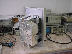
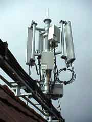
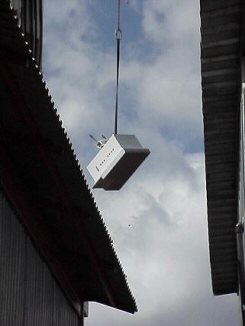
The RF part is in a weather proof
container between the coaxial cable and the antenna. There is a diplexer
on each input (ANT, BTS) separating the signals in the Tx and Rx
directions. DC power is supplied to the container through the inner
conductor of the coaxial cable.
An indoor Power Supply and Alarm Cabinet
(part of the DTRA 900 GSM) provide DC power through a bias-Tee DC
separator. One indoor cabinet can supply two outdoor RF containers.
The transmission amplification can be set
locally. A built-in test circuitry controls both the Tx and Rx branch
operations visually displayed by the indoor Power Supply and Alarm
Cabinet. Besides the main parameters the antenna reflection is also
measured and displayed (VSWR monitoring). The status information of the
main parameters are also put out to relay contact pins for outside
remote management. If errors, high antenna reflexion or power supply
outage occur the Tx or Rx branches immediately switch to bypass operation
without any interrupt in the connection.
There is a PC connection possibility to
provide an additional quantitative analysis for easy error location as
well.
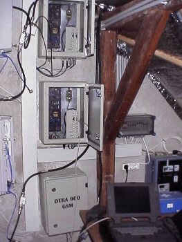
For more Photos on real installations go to services...
Technical data
|
- Type |
DTRA 900 GSM |
|
|
Frequency band
- Tx Band (BTS)
- Rx Band (BTS)
- Bandwidth
- Tx - Rx Distance |
partial P-GSM band
935 - 960
890 - 915
8
45 |
MHz
MHz
MHz
MHz |
|
No. of Tx Channels |
1 |
|
|
Temperature range
- outdoor equipment
- equipment |
-25...+55
0...+45
|
0C
0C
|
|
Storage Temperature |
-35...+65 |
0 C |
|
MTBF |
150 000 |
h |
|
OUTDOOR EQUIPMENT |
|
|
|
Tx Branch (BTS ->
ANT) |
|
|
|
Input Level Range |
0,01 - 2
(10 - 33) |
W
dBm |
|
Max. Input Level with no error |
5 |
W |
|
Nominal Gain
(between ANT and BTS clamps) |
14 - 12 - 10 |
dB |
|
Control of Gain |
2 - 4 |
dB steps, from outside |
|
Control Accuracy |
± 0,5 |
dB |
|
Amplification Level Dependency |
± 0,5 |
dB |
|
Temperature Dependency
(In the entire temperature range compared to the normal
temperature range) |
+1 / -2 |
dB |
|
Output Shutdown Threshold Value
|
max. 30
|
W
|
|
Output Level to be Tuned |
max. 20
(max. 43) |
W
dBm
Note: amplification has to be set to the given input level |
|
Fluctuation in Pass Band |
max. ±
0.5 |
dB |
|
Return Loss (BTS, ANT) |
min. 16 |
dB |
|
Tx – Rx Separation |
min. 65 |
dB |
|
BYPASS Status Characteristics |
|
|
|
Insertion Loss (BTS -> ANT) |
max. 2,5 |
dB |
|
Return Loss (BTS, ANT) |
min. 16 |
dB |
|
Rx Branch (ANT ->
BTS) |
|
|
|
Noise Figure
- in normal temperature range
- in extreme temperature range |
max. 2
max. 2,5
|
dB
dB
|
|
Gain (ANT -> BTS) |
14 ±
1 |
dB |
|
Fluctuation in Pass Band |
max. ±
0.5 |
dB |
|
Return Loss (ANT, BTS) |
min. 16 |
dB |
|
Group Delay Distortion |
130 ±
30 |
ns) |
|
Third Order Intercept Point (IP3)
(measured on BTS output) |
min. 20
tip. 27 |
dBm
dBm |
|
Intermodulation Rejection
for ANT input as below:
1./ Rcvd Signal (ANT):-35 dBm
2./ Tx Signal (BTS): +30 dBm;
1./ Rcvd Signal (ANT):-35 dBm
2./ Rcvd Signal (ANT):-35 dBm;
1./ Tx Signal (ANT): +43 dBm
2./ Rcvd Signal (ANT):-35 dBm. |
max. -115
|
dBm
|
|
BYPASS Status Characteristics |
|
|
|
Insertion Loss (ANT ->BTS) |
max. 2,5 |
dB |
|
Return Loss (ANT, BTS) |
min. 16 |
dB |
|
Connector (on input and output)
- type
- impedance |
7/16 neg.
50
|
ohm
|
|
PC/Notebook interface |
RS232 S |
|
|
Power Supply |
+30 ±
1 |
V DC |
|
Current Consumption |
max. 4
tip. 3,5 |
A
A |
|
Mechanical Construction
- size (without support assembly)
- weight
- installation |
483 x 300 x 220
24
|
mm
kg
on horizontal or vertical pole of Æ
110 max.
|
|
INDOOR EQUIPMENT |
|
|
|
Temperature Range |
0....+45 |
0 C |
|
DC and Signal Separator
(DC900/33) |
|
|
|
RF Frequency |
890 - 960 |
MHz |
|
Insertion Loss |
max. 0,3 |
dB |
|
Return Loss |
min. 25 |
dB |
|
Output Power |
max. 50 |
dBm |
|
Current Load |
max. 5 |
A |
|
DC-RF Separation |
min. 110 |
dB |
|
Signaling Frequency |
5,4 / 5,6 |
MHz |
|
Connector Type
- to BTS
- to cable
- DC and signal input |
7/16 pos.
7/16 neg.
XLR
|
|
|
Compact Size (without connectors) |
35 x 60 x 103 |
mm |
|
Weight |
0,3 |
kg |
| |
|
|
|
Power Supply and Signal Cabinet
(DTRA-B) |
|
|
|
No. of Supplied Outdoor Units |
2 |
|
|
Local Alarm Signals
|
|
1./ Tx Branch Error (green
or red LED)
2./ Rx Error (green or red
LED)
3./ High Antenna Reflexion
(green LED row) |
|
Information sent to Remote
Management |
|
The above data led to
opening and/or closing
relay contacts) |
|
PC/Notebook interface |
RS 232 S |
|
|
Power Supply Data |
|
|
|
Input Voltage |
230 ±
10 %
50 / 60 |
V AC
Hz |
|
Output Voltage |
+30...+33 |
V DC (adjustable) |
|
Mechanical Construction |
|
Wall- or vertical plane-
mounted cabinet with
lockable door. |
|
Compact size (H x W x D) |
400 x 300 x 220 |
mm |
|
Weight |
10 |
kg |
Manufacturer reserves the
rights to make any technical data changes irrelevant to base
specifications. |