|
DLNA 900
GSM Antenna Diplexer
(Sponsored by Westel 900 GSM Rt.)
Table of contents:
1. General Description
2. Structure
3. Technical Description
3.1. Outdoor Container
3.2. Power Supply and Indicator Cabinet
3.3. Indoor DC Separator
4. Technical Parameters |
 |
1. General Description
The DLNA 900 GSM antenna diplexer is used on the base stations
of the GSM 900 mobile telephone system. It extends the receiving
sensitivity of the base station that uses the same transceiver antenna.
This way the signal coverage area is enlarged. At the same time, within
the GSM cell, the connection between the subscriber and the base station
will be more stable.
The DLNA 900 antenna diplexer is placed near the antenna,
between the coax connection cable coming from the base station (BTS) and
the antenna connection (ANT). The diplexer separates the transmitter and
receiver signals coming from both the antenna (ANT) and the base station
(BST) as per the signal's direction. At the same time a low noise
preamplifier (VLNA 900) is placed in the way of the receiver signal(s)
coming from the antenna. The amplified signal(s) are then sent to the
shared cable connection (BTS). In the transmission direction the
transmitter signals are sent to the antenna connection (ANT) via a low
attenuation transmitter filter. The high selectivity receiver filters of
the diplexer make sure that the high level transmission signals do not
get into the receiver branch amplifier thus causing over-control or
intermodulation mixture. In case the active circuit (low noise pre
amplifier) breaks down, or there is power shortage, the bypass operation
mode will start. This means that the signal route goes around the
amplifiers via relays but the connection will stay alive. In other words
there is no service outage, only the connection's parameters are
deterred until the problem is fixed.
The local alarm circuit of the indoor power supply and the indicator
cabinet, as part of the system, visually show the normal operation
(green LED) or alarm (red LED) status of the system. At the same time
this information is taken to Morse relay contacts that can be connected
to the remote management system of the station. One, fully configured
cabinet is able to manage the unified signals from 6
transmitters/receivers.
The outdoor unit containing the diplexer and the low noise
preamplifier is in a hermetically closed weatherproof container
protecting the unit against climate changes. The basic configuration
enables connection to both horizontal and vertical masts. Summarizing
the above, the DLNA 900 diplexer is offering the following
functions and advantages to the user:
-
enables the use of the same antenna for both the transmitter and the
receiver.
-
the low noise amplifier added to the receiving branch, as part of the
system, disables cable attenuation thus increasing receiver sensitivity,
which equals the enlargement of the BTS coverage area
-
in transmission direction the low attenuation with high selectivity
filter added in the path of the transmitter signal lowers the emitted
signal level only, while providing enough attenuation on the receiving
frequency not to absorb any of the receiving signal.
-
the receiver filters of the diplexer, besides the low passband
attenuation, have a significant closing band attenuation to the nearby
transmission signal. This way the highest allowed level transmission
signals cannot cause a disturbing signal comparable with the level
of the possible useful receiver signal (neither directly nor in a
mixture format.)
-
any alarm of the amplifier or power shortage make the bypass mode come
on, this way there is no drop in the connection.
-
local display, system operation status and remote management
information is available
-
the system is easy to install. The outdoor container can be connected
to either horizontal or vertical masts. The indoor power supply and
indicator cabinet can be installed on the wall (or a vertical pane).
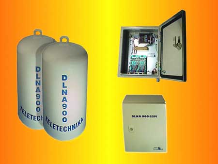 Figure1 Figure1
2. Structure
Figure 1. shows the layout structure of the system and how the DLNA
900 GSM system can be connected to an existing base station.The outdoor container with the antenna diplexer is fixed to a mast
holding the station's antenna assembly. A short jumper cable connects
one of the 7/16(-) connectors of the container to the shared transceiver
antenna while the coax cable connecting the outdoor and indoor units of
the equipment is connected to another similar 7/16(-) connector (BTS).
(These coax cables are already part of the base station).
There is a power supply separator installed on the unified RF output of
the base station (BTS). The separator ensures that the necessary 7/16
type RF connectors have negative/positive (female/male) outlets this way
the existing cables can be used without alterations and the DC
connection spot is obvious. The +15V nominal voltage DC shielded cable
has to be connected to the XLR connectors. The other end of the +15V
cable is connected to the power supply cabinet.
The -48V primary power supply of the equipment is connected to the power
supply and indicator cabinet. The XLR DC connectors and the D-SUB
connector containing the contact outlets for the remote management are
on the shared lower connector panel. (For better viewing Figure 1. shows
outlets supplying only one transceiver.)
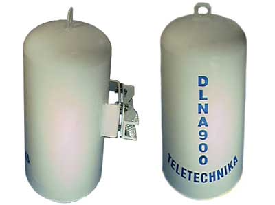 Figure2. Figure2.
3. Technical Description
3.1. Outdoor Container
The theoretical operation of the outdoor container is shown on the
following block scheme outline (Figure 2.). From transmission direction
the incoming signal from the shared cable to the BTS connector goes
through the DC separator to a shared resonator. From here the only way
for the signal to go is in the transmission filter because the steep
slope Receiver Filter 2 reflects the signal from the other input. The
transmission signal is sent through the signal filter and the ANT side
shared resonator to the ANT shared antenna connector. From the
construction's point of view, the transmission filter includes 5 high
quality inductive connection coax resonators. While having only 0,5 dB
pass attenuation it also has significant reflection to the operational
receiver band in the operational passband.
In receiving direction the signal coming from the antenna goes through
the shared cavity to the Receiver Filter 1 from where it goes to the
VLNA 900 low noise amplifier. The Receiver Filter 1 includes 7 high
quality inductive connection coax resonators. The Receiver Filter 1 has
to prevent high level transmission signals from getting into the low
noise amplifier, this way the level of the intermodulation mixtures made
up of the transmission signals and the transmission and receiver signals
will be lower than the threshold of the useful receiver signal. Another
two suction loops are included in the output resonator in order to
achieve a higher depression of the third grade intermodulation product
on the critical points of the receiver band (935-940 MHz).
The primary role of the VLNA 900 low noise preamplifier is to lower the
derived noise factor of the entire receiver side. This is possible
because the attenuation of the connecting coax cable is out of the noise
scale due to its low noise factor and amplification. Even with shared
antenna usage, the receiver direction hop attenuation is lowered by a
value complying to the cable attenuation. Another requirement from the
amplifier is that it have high IP3 (third grade intersection) value
contrary to the transmission signals appearing on the shared connector
and to the high level receiver signals mixture (which is allowed in the
specification but in reality is very unlikely).
Should any alarm occur in the amplifier the connection will go down.
There is a bypass in this case; when alarm occurs the Morse type relays
at the amplifier input and output will open and the connection stays on
through the route going around the active circuits even at 1 dB quality
deterioration until the error is corrected.
Power is supplied to the amplifier by the DC separator which has a lower
pass filter type high frequency conductor making sure that the RF
signals cannot seep through to the amplifier neither galvanically nor
through scattering. From the amplifier output the receiver signal goes
to the output side Receiver Filter 2.
The difference is that for the protection of the amplifier outlet it is
not necessary to have additional suction loops, as the 7 resonator
filter provides enough protection against the BTS side transmission
signals.
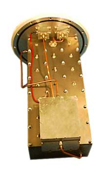
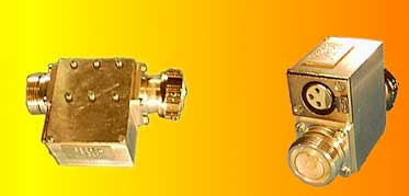
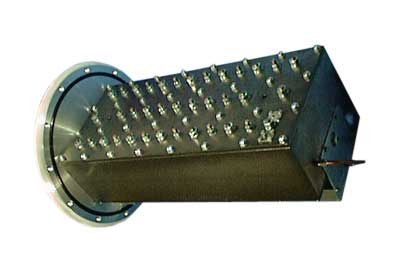
The mechanical structure of the outdoor container is shown by Figure 3.
The transmission filter and the two receiver filters are in a single
cut-out block (diplexer). The amplifier (VLNA) is built in a separate
shielded metal housing. The signal is sent to the receiver filters
through the SMA connectors and semi rigid cables on the amplifier box.
The cut block containing the filters and the amplifier are secured on
the closing lid of the container.
One of them is the DC separator; as the amplifier gets the +15V DC
voltage through its high frequency conductor.The rubber ring (not shown
in the drawing) installed in the slot on the closing lid and one part of
the mast support assembly can be initially fastened to the U-holder
welded to the outdoor container. The other part of the support assembly
has to be assembled to the mast during the on-site installation. The
following drawings show how to secure the container to horizontal or
vertical masts. The housing of the container is made of drawn aluminum.
The outside is coated with oven baked fiber glass special compound. The
outside connecting assemblies are made of corrosion proof material.
Figure
3
3.2. Power Supply and Indicator Cabinet
The cabinet can be installed on the wall or on any vertical panel, in
its full configuration supplies +15V to six VLNA 900 low noise pre
amplifiers from the outdoor containers in such a way that a printed
circuit card serves two amplifiers (Panels 1, 2 and 3). In its
basic configuration two printed boards are installed in the cabinet. A
shared DC/DC converter receives the incoming primary (battery) power.
The amplifiers have a built-in self- monitoring control system. It emits
visual signals for the local control: normal operation mode is indicated
by a green LED, the alarm mode is indicated by a red LED. The circuit
evaluating the performance also controls a Morse relay. The relay
contacts' outlets are on the connector panel and this way are available
for the remote management system.
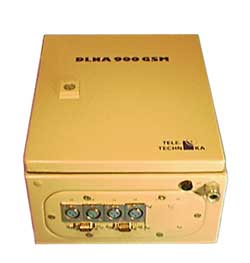
The connector panels on the bottom of the cabinet contains all
connectors necessary for the user. Figure 6. shows the connector panel
with connector positions. As it is shown, the ascending +15V power for
each amplifier appears on the XLR connector that has to be cable
connected to the similar connection type indoor DC separators (1A, ...,
3B).
The corresponding panels' remote management contact band outlets are on
connectors CS1 ... CS3 D-SUB (often used in computer technology) as
follows:
Amplifier Mark, Normal mode, Alarm Mode
A, 9-5: RZ 9-4: SZ, 9-4: RZ 9-5: SZ
B, 3-2: RZ 3-1: SZ, 3-1: RZ 3-2: SZ
The -48V primary power supply cable has to go through the
"INPUT/-48V" clamp on the panel and the 6A fuse has to be
inserted directly in the connecting bar of the DC/DC converter.
The power supply and indicator cabinet has a lockable door. The cabinet
is supplied with a connection necessary for the protective grounding. In
basic configuration the cabinet has 2 panels, the third panel can be
installed on-site.
3.3. Indoor DC Separator
The indoor DC separator can be directly connected to the 7/16 unified
transceiver outlet of the base station frame, while its connection to
the ascending coax cable is similar to the frame outlet 7/16(-). The
power supply (+15VDC) is connected through the XLR type connector.
The DC separator has to establish a power supply for the low noise
amplifier through the inner conductor of the ascending coax cable with
input side separation in such a way that the attenuation to be
established RF signal route be the minimum, the reflective attenuation
in both bands be the maximum and the RF seeping towards the power supply
input be highly suppressed.
The structure DC separator without cover is shown in Figure 7. below.
The serial C condensation established in the RF route to the BTS
separates the DC. Towards the power supply the F throttle and the SZ
through filter prevents the RF signal to exit towards the DC input. The
D1 diode installed parallel on the DC input protects against overcharge
(lightning). The RF transmission route can be tuned to minimal
reflection in the entire transmission band by the tuning islands welded
between the DC (not indicated on the drawing).
For more Photos on real installations go to services...
4. Technical Parameters
FREQUENCY BAND
|
As per GSM 900 |
|
| - Receiver |
890 - 915 |
MHz |
| - Transmitter |
935 - 960 |
MHz |
OUTDOOR UNIT
|
|
|
-Transmitter Branch
(BTS to ANT)
|
|
|
| Passband Insertion Loss |
0.5 max. |
dB |
| In-Band Fluctuation |
+/- 0.1 max |
dB |
| Reflection Loss |
16 max. |
dB |
| Transmitter Output Power |
47 max. |
dBm |
Group Delay Distortion
(BTS to ANT) |
80 +/- 20 max. |
ns |
| Infinite VSWR |
No Damage |
|
-Receiver Branch
(BTS to ANT)
|
|
|
| Pass-Band Fluctuation |
+/- 0.5 max |
dB |
| Noise Figure |
|
|
| T=25 C |
1.7 max. |
dB |
| T=65 C |
2.1 max. |
dB |
| Third Order Intercept Point |
27 min. |
dBm |
| Reflection Loss (ANT, BTS) |
16 min. |
dB |
| Group Delay Distortion |
120 +/- 25 max. |
ns |
General Data of the Outdoor
Unit
|
|
|
| MTBF |
150,000 |
h |
| Connector type |
coaxial, 50 Ohm |
|
| -ANT port |
7/16 (female) |
|
| -BTS port |
7/16 (male) |
|
| Mounting |
Mast is preferred |
|
| Diameter of mast |
110 max. |
mm |
| Position of mast |
vertical or horizontal |
|
| Temperature Range |
|
|
| -operating
status |
-25 C to +55 C |
|
| -storage |
-35 C to +65 C |
|
| Projection against lighting |
As per IEC 1024 |
|
Machanical Construction of the Outdoor
Part |
Weatherproof Container |
|
INDOOR Unit Assembly
|
|
|
| DC By-Pass Adapter |
|
|
| Frequency Band |
890 to 960 |
MHz |
| Insertion Loss |
0.2 max. |
dB |
| Reflection Loss |
25 min. |
dB |
| Max. allowed RF Power |
50 |
dBm |
| DC to RF Isolation |
110 min. |
dB |
| Current Load |
2 max. |
A |
| Connector Type |
coaxial, 50 Ohm |
|
|
-BTS Port |
7/16male |
|
DLNA 900 Power Supply and
alarm Unit
|
|
|
| No. of Outdoor Units to drive |
max. 6(3 PCB cards) |
|
| Basic mounting |
4(2 PCB cards) |
|
| Visual display of the operation |
|
|
| - normal
operation |
green LED |
|
- alarm
(by-pass or decoupled
cable) |
red LED |
|
| Remote Control Acces |
relay contacts: |
|
| -1 status |
- short circuit |
|
| -2 status |
- open circuit |
|
| Mechanical Construction |
Box to be mounted on the wall |
|
|